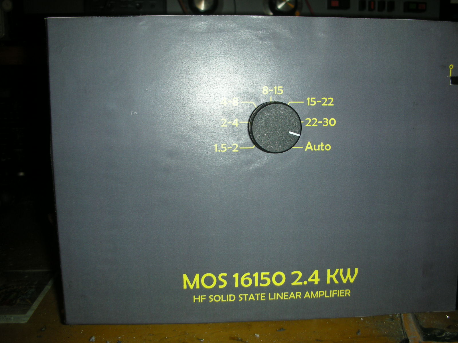
1. Specifications Frequency : 1.8 ~ 30 MHz all amateur bands including WARC bands Mode : SSB, CW, RTTY RF Drive : 85W typ. (100W max.) Output Power : 2.4 kW (typ.) Matching Transceivers for Auto Band Decoder : Most ICOM, Yaesu, Kenwood ,Auto sampling rf in , Manual Drain Voltage : 42 V Drain Current : 100 A max. Input Impedance : 50 Ohm (unbalanced) Output Impedance : 50 Ohm (unbalanced) Final Transistor : MRF150 x 16 Circuit : Class AB push-pull Cooling Method : Forced Air Cooling MPU : PIC 16F877 Reflected Power Pr 300W Input/Output Connectors : UHF SO-239 with low loss Teflon insulator AC Power : AC 240 V (200/220/230/250 V) 25A max. AC Consumption : 4.5 kVA max. when TX Dimension : 490 x 190 x 380 mm (W x H x D) Weight : Approx. 12 kgs. RCA Plug (Stereo Type Pair Cable) x 2 Band Decoder
2. Features 2-1 Our solid-state broadband design engineers worked to make the MOS16150, the lightest 2.4 kW HF amplifier. This world-class compact 2.4kW HF amplifier is the easiest to handle and operate.
2-2 The amplifier is equipped with a newly developed band decoder. The amplifiers decoder changes bands automatically as the data signal is received from the associated HF transceivers frequency bands.
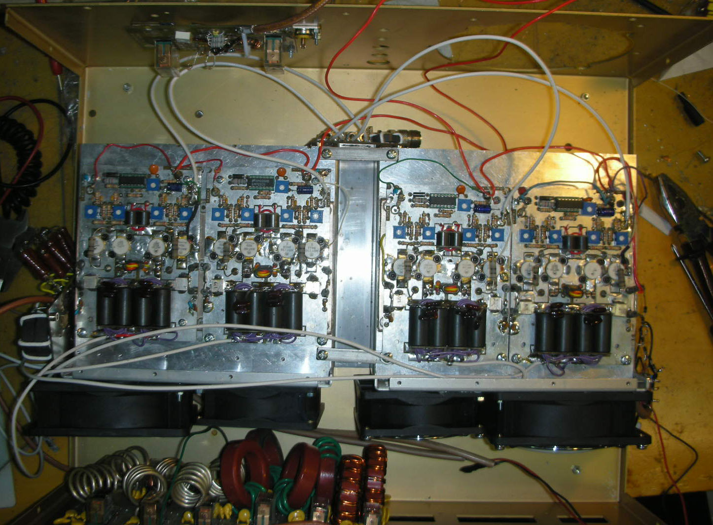
2-3 The amplifiers main PA section includes 16 high power MOS FET MRF150, resulting in 2.4 kW (SSB max.). The amplifiers broadband characteristics require no further tuning.
2-4 The amplifier allows operation in full break-in CW mode due to the use of the amplifiers high- speed antenna relays (made by Panasonic/Matsushita).
2-5 With the unique duct structure design and the powerful blower fan, the aluminum heat sink block for RF PA module (and other components), are effectively cooled. The fans quiet operation.
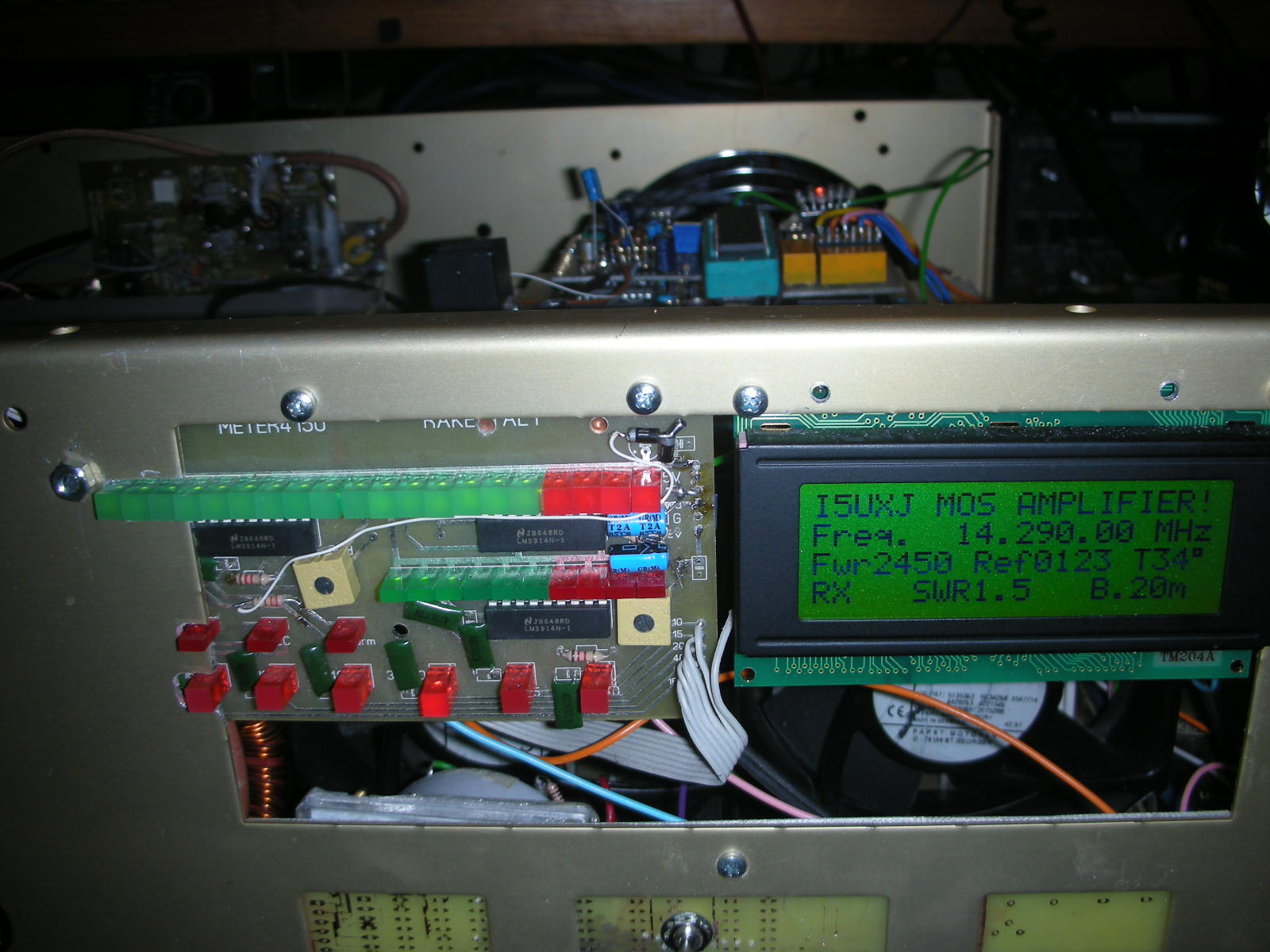
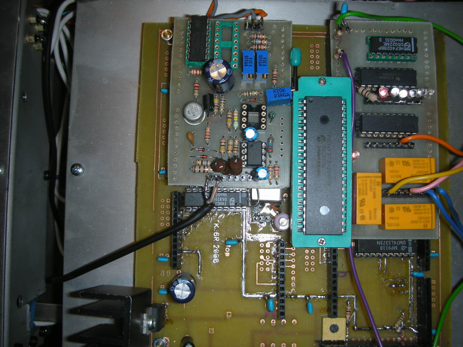
2-6 The amp utilizes an advanced 8 bit MPU (microprocessor) to run the various high speed protection circuits such as overdrive, high antenna SWR, DC overvoltage, band miss-set etc.
Automatic band change based on rf input or by cable for yaesu and icom RTX
Microprocessor assisted for band change and protetction : ros , temperature , fan speed
Output circuit revised , the original EB104 do not perform ok in all band , efficiency improved
The
experience with the EB 104 started about 2 years ago; the first test have been
done only with one module, the results were not very good.
The results
at 50V were: 1) very low performance 2) the C11 capacitor was used to
optimize the 160 Mt band but with a degrade in the 10 mt. band and vice-versa
3)there was too much heat to dissipate 4)in presence of VSWR the mos-fet
were at very high risk of burning The T3 trransformer were not matching
correctly the impedance.
After that we lower the voltage at 40V and we
found that the performance was much better The output power stays almost the
same with the same current and this confirm that there were impedance matching
problems. We still had the problem to cover all the bands. After having
redesigned the T3 transformer, we achieved the full coverage at full power of
the entire band starting at 160 mt till to 10 mt. and we could bring the
voltage at 42V. the performance now at full power is about 55% while
at lower power it drops till 30%. For a use with continuous carrier with a
lower power it is advisable to lower the voltage at around 30V using the
amplifier at maximum power that in this case will be around 350W and the
performance around 65%. At 42V when at 350W, the performance is 40% and the
heat is similar that the one at full power At this point we decided to
switch to the configuration composed by 2 modules coupled through the PSC-2
coupler by Communication Concept. The output power was the same that using
only one module, basically the system was not working. After various tests
without any success, we decided to test the PSC-2 with the network analyzer (HP
8753C) and we immediately found the evidence of why the system was not working:
the output impedance of the PSC-2 was 11 ohms instead of 50 ohms. I will
post pictures of the measurements taken with the network analyzer. At this
point we see 2 possibilities; 1) My PSC-2 has been built in a bad way
(it can happen) 2) The project of this coupler is wrong
With the
network analyzer we have made some changes in the coupler so tha we have
obtained 50 ohms output impedance. Once that we have tested the coupler
after the changes, we immediately got the power doubled; we now have around
1200W all over all the bands. From there we passed to a 4 module
configuration; this time the PSC-4 was working perfectly and we immediately got
2400W all over the bands.
The PSC-4 coupler also if the technical
specifications are for lower power, performs well in SSB. It is clear that it
cannot be used for continuos carrier because it becomes too hot in a very short
time. This coupler is cooled by the flux of the air.
With the
amplifier powered at 42 volts and current around 90 amps in many cases the
amplifier (because of mistakes) has suffere SWR very high close to infinite;
some times still by mistake we have activate the transmission without beeing
connected to the antenna or with the filter selected in the wrong band; it
never happened a problem, no mos-fet burned (it only happened when we tested one
module with 50 volts)
We have designed a microprocessor program that
handles all the protections; we inhibit the amplifier at SWR higher than 3.0 and
power higher than 600W. That means that with lower power the amplifier can
operate also with higher SWR. There is another protection for high
temperature and one for the driving power. We also have an hardware
protection before the filters; in case of mismatching due to filter problems the
amplifier is inhibit. The microprocessor also controls the fans with 3
different controls; fans are off till the reach of 38 degrees Celsius, fans at
half speed up to 50 degrees and fans at full speed over that level. To get a
good heat dissipation we used a heatsink with elements 80 mm high and 4
120mm fans by PAPST. The fans are 36-58V but they are powered with 27 volts
so they are very silent with a very good air flow.
More info , photo , data , will be publish in next
days, this only preliminar page with old photo.
Numero accessi a questa pagina dal 5/12/08- Totale
Inviate i vostri commenti e le vostre richieste a:Alfredo Rosati I5UXJ-KJ6R alfredo@cln.it
Page updated 02-11-2008
solid state hf linear amplifier amplificatori lineari hf home made con 4cx800 gu74b mrf 150 eb104 3cx1200a7 gs35b 4cx250 gu84b per ulteriori informazioni e schemi di montaggio scrivere via email ad alfredo@cln.it
 HOME MADE Solid State HF Amplifier with 16 mrf150
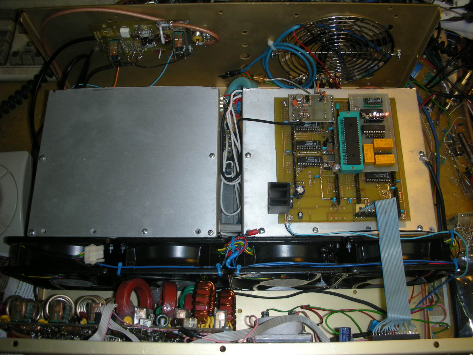
![[Count not available in text mode]](../../cgi-bin/Count7b29.gif?ft=0&df=amp150.dat)